Roshanray F, Sandler C Root resorption: why we all need to get informed consent. Orthod Update. 2023; 16:707-709
Brezniak N, Wasserstein A Orthodontically induced inflammatory root resorption. Part I: The basic science aspects. Angle Orthod. 2002; 72:175-179
Imai A, Takamizawa T, Sugimura R Interrelation among the handling, mechanical, and wear properties of the newly developed flowable resin composites. J Mech Behav Biomed Mater. 2019; 89:72-80 https://doi.org/10.1016/j.jmbbm.2018.09.019
Occasionally, treatment modalities fall short of the expected outcomes. In the case study presented, the patient's orthodontic treatment had to be abandoned abruptly owing to excessive root resorption affecting the upper and lower incisors. This left the patient with unsatisfactory aesthetics and a suboptimal occlusal set up. The signs of tooth wear, combined with reduced periodontal support as a result of resorption, meant that occlusal management in this case was just as important for long-term success and stability as aesthetic planning.
CPD/Clinical Relevance: The case presented demonstrates how to plan and execute both aesthetic and occlusally focused treatments in a minimally invasive and predictable manner.
Article
In the pursuit of aesthetics and functionality, clinicians often encounter complex cases requiring interdisciplinary collaboration and innovative approaches. This case study highlights a scenario where a patient presented with challenges from complications of orthodontic treatment, ultimately necessitating corrective restorative intervention.
Case presentation
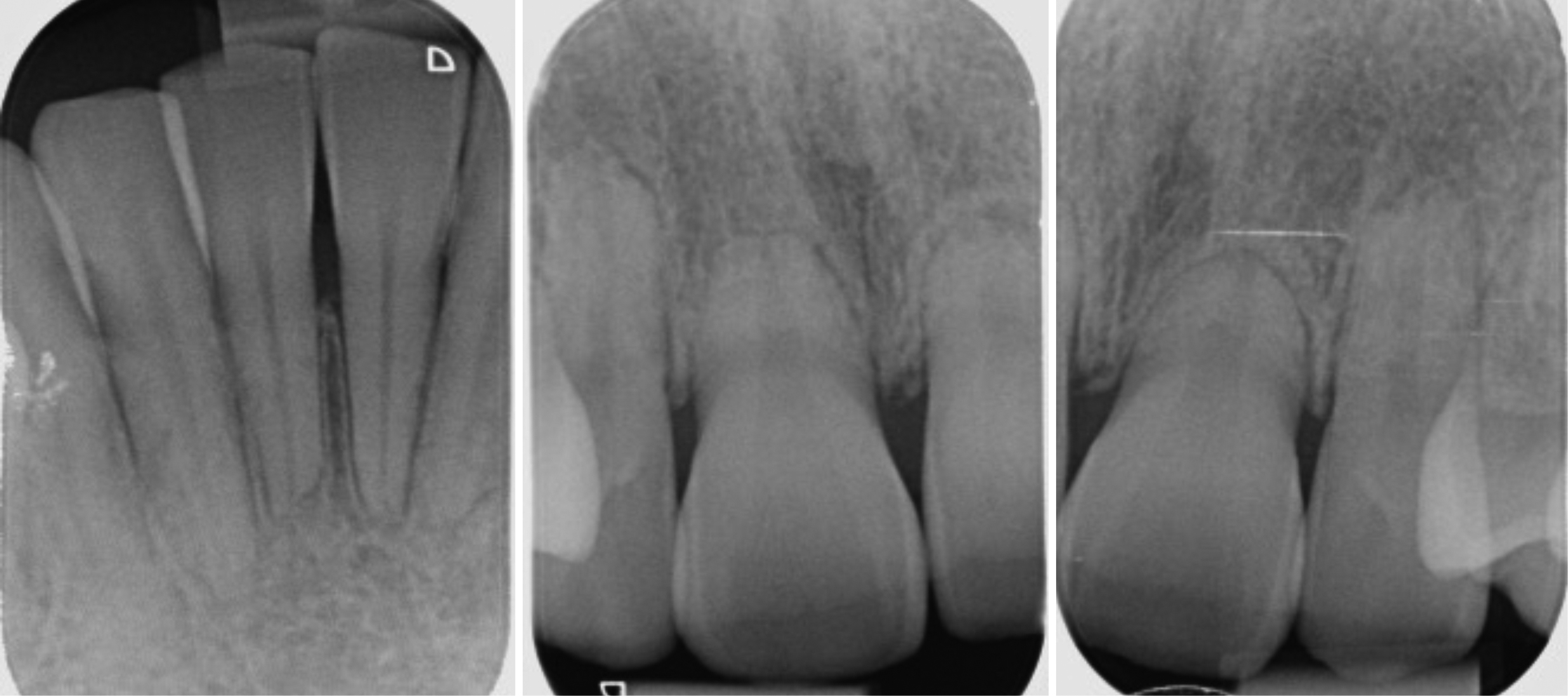
A 28-year-old female was referred to the clinic by her orthodontist owing to complications arising during orthodontic treatment. The patient exhibited severe root resorption of the upper and lower central and lateral incisors, necessitating the cessation of orthodontic treatment. Apical root resorption is an undesirable side-effect of orthodontic treatment, and it is considered severe when 4 mm or one-third of the root length has resorbed.1 Severe apical root resorption has a reported incidence of between 1% and 5% of orthodontic cases.2 Figure 1 shows the radiographic extent of the resorption. The central incisors exhibited near grade 1 mobility, with less pronounced mobility on the lateral incisors.
Figure 1. (a–c) Peri-apical radiographs confirming apical root resorption, with the upper central incisors worst affected.
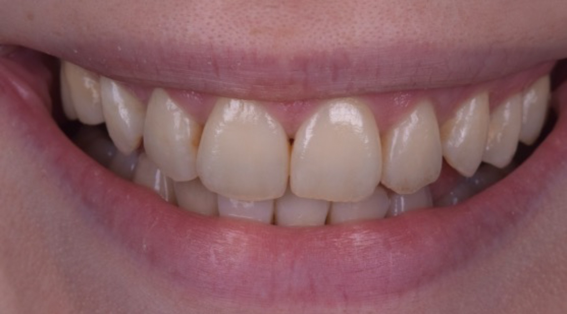
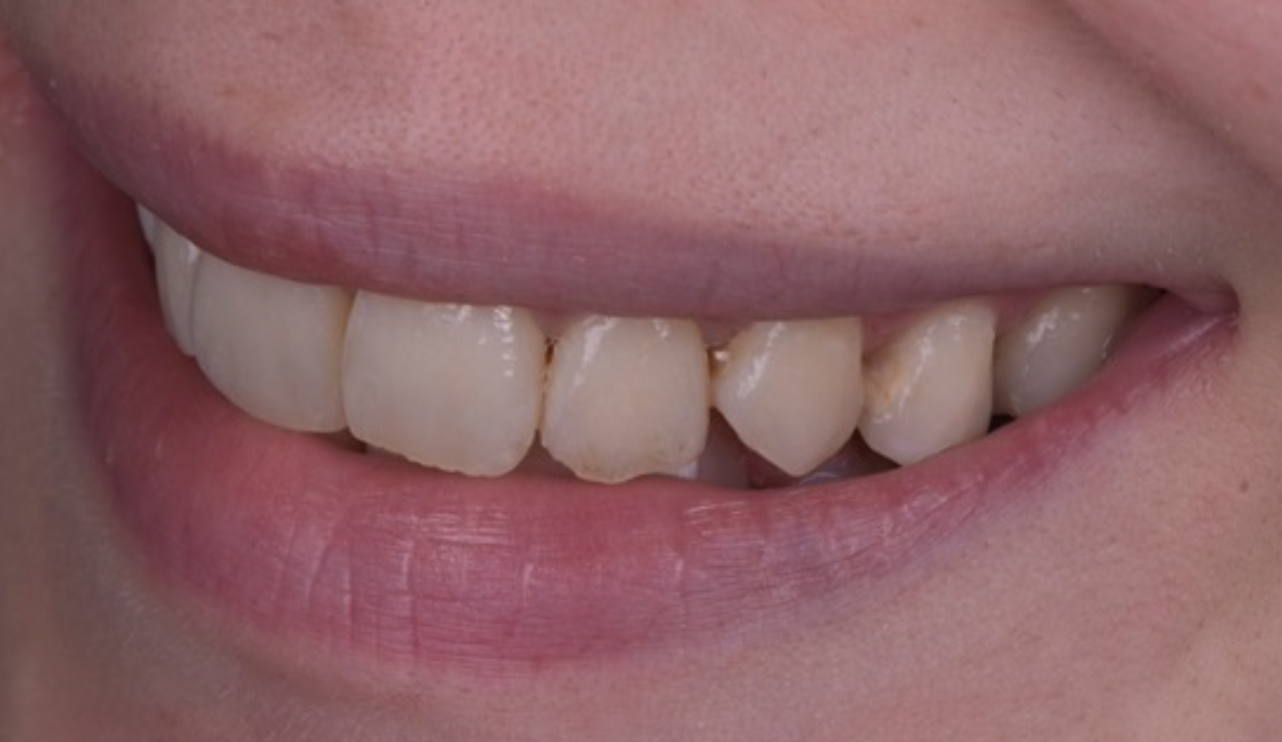
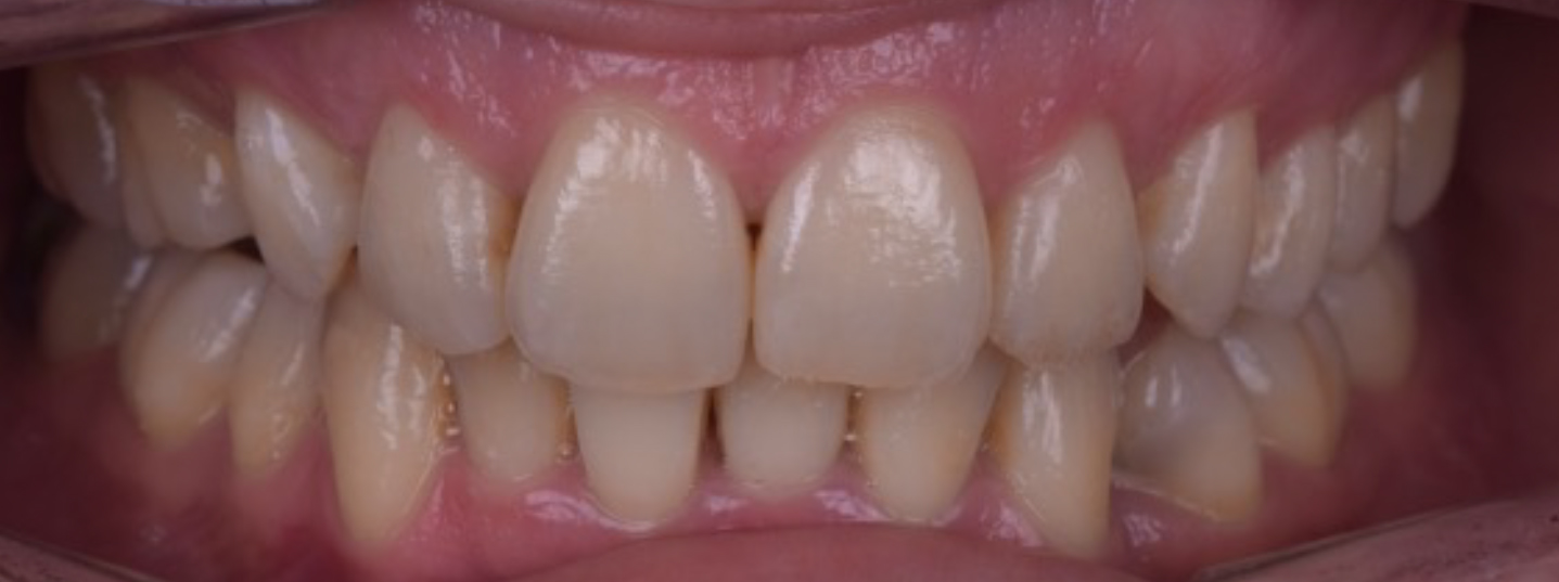
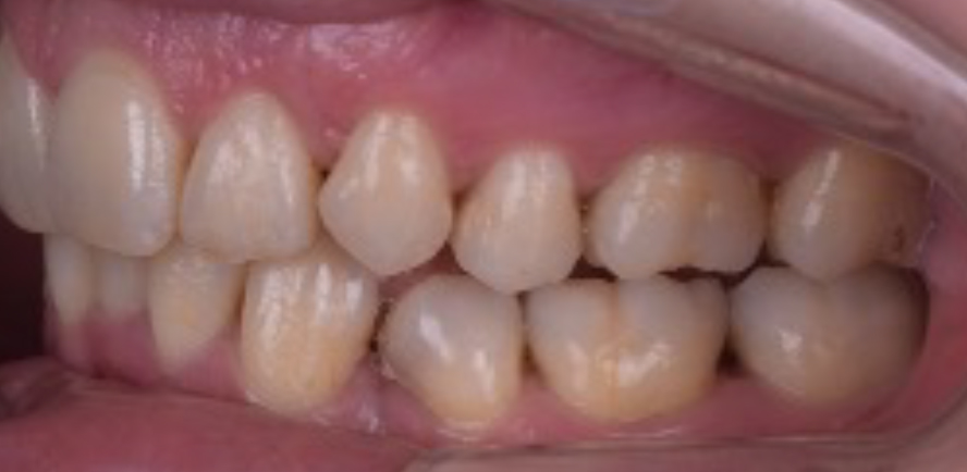
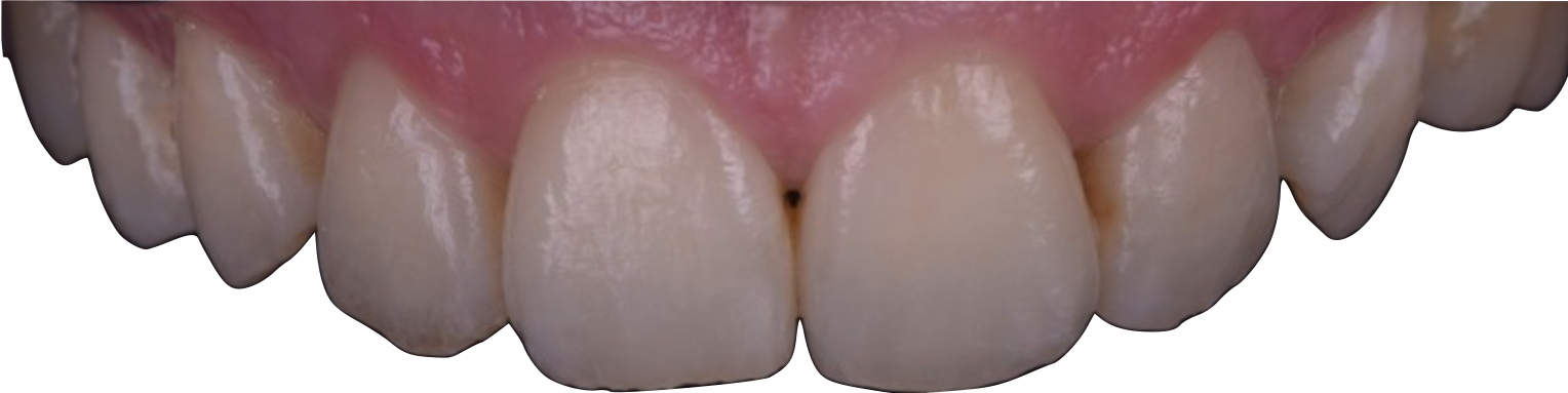
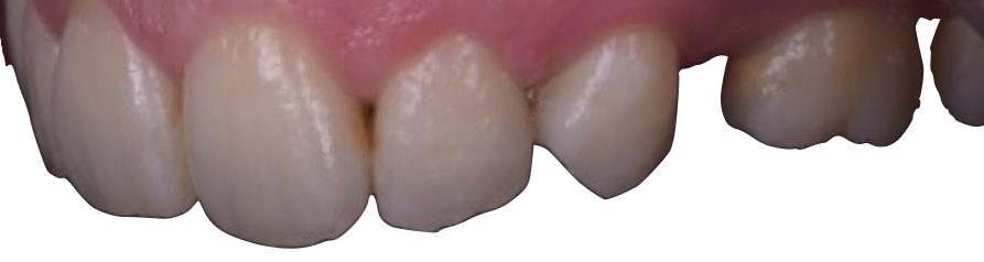
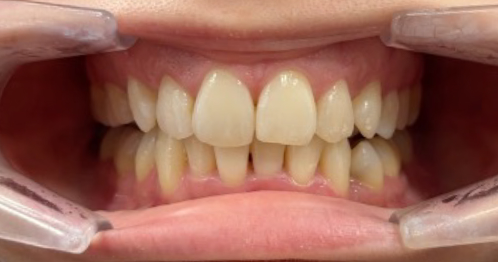
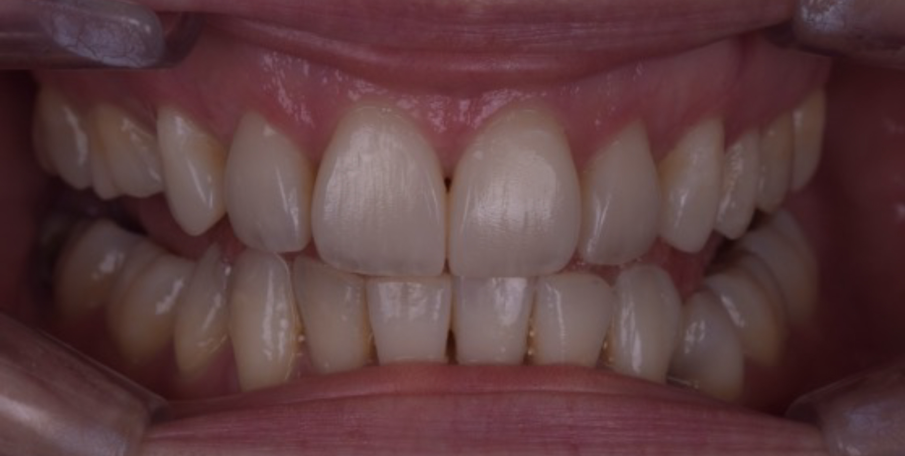
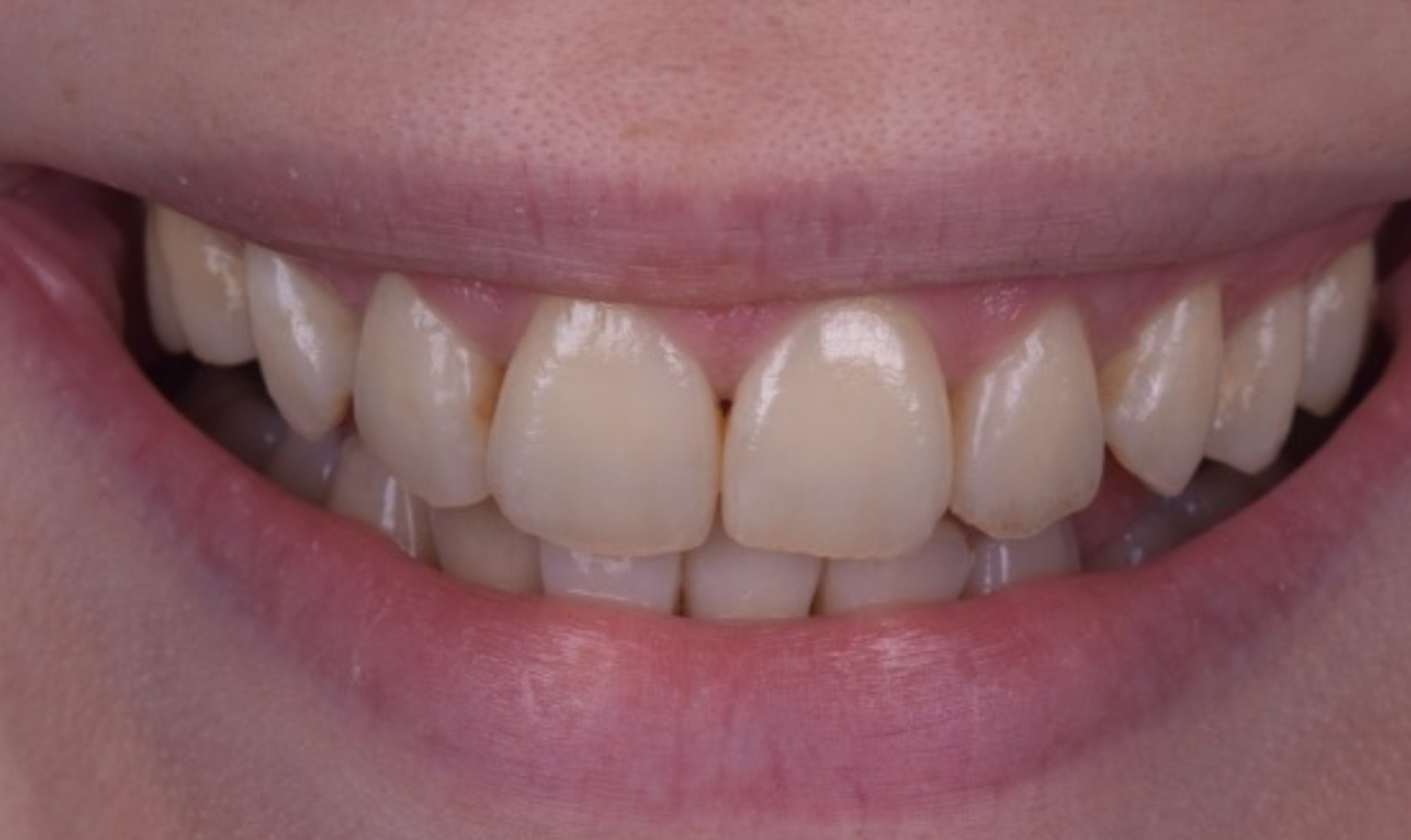
The patient was unhappy with the aesthetics of her smile after the brackets were removed, complaining about the unevenness of the teeth and the residual space present where UR5 had been extracted (Figures 2 and 3). The upper canines were extracted prior to the orthodontic treatment because they were very buccally placed. The aim had been to close the residual space between UR6 and UR4 orthodontically, but unfortunately, it had not been possible because orthodontic treatment had to be abandoned (Figure 4).
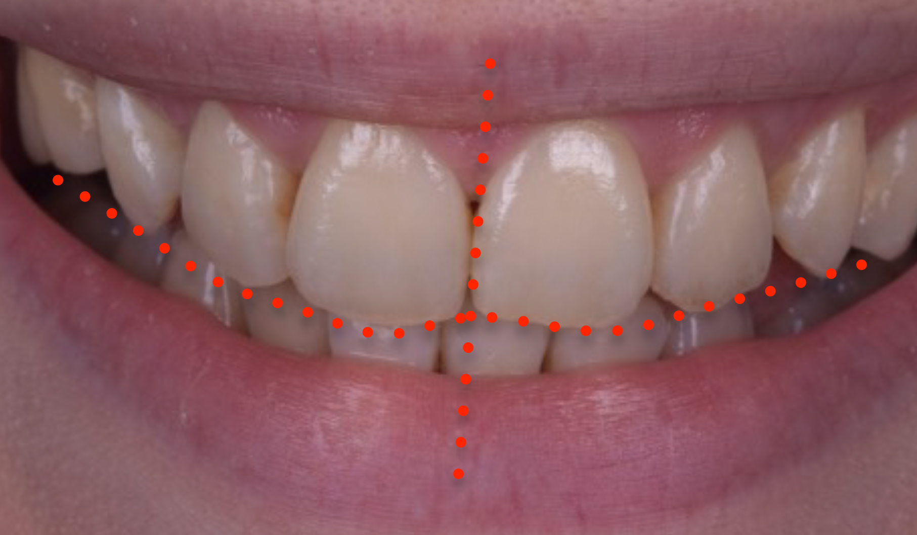
Figure 2. Initial presentation.Figure 3. Note the canted midline and canted incisal plane.Figure 4. Right smile shot showing missing UR4 and residual space.
The patient had no relevant medical history and had a healthy dentition with minimal restorations. She was particularly concerned about preserving her existing tooth structure and understood the potential long-term impact of resorption on her front teeth. With an emphasis on maintaining the integrity of her teeth, she was cautious about any procedures that might compromise them further. Her oral hygiene was excellent, and she was a non-smoker, which contributed positively to her overall dental health.
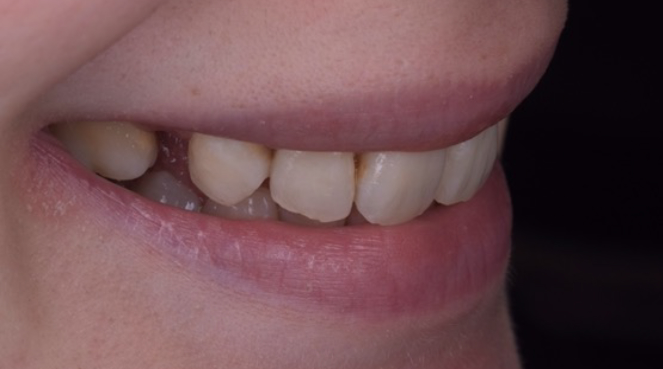
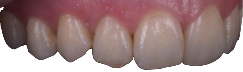
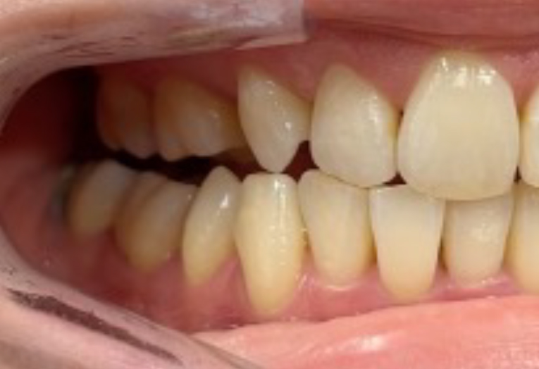
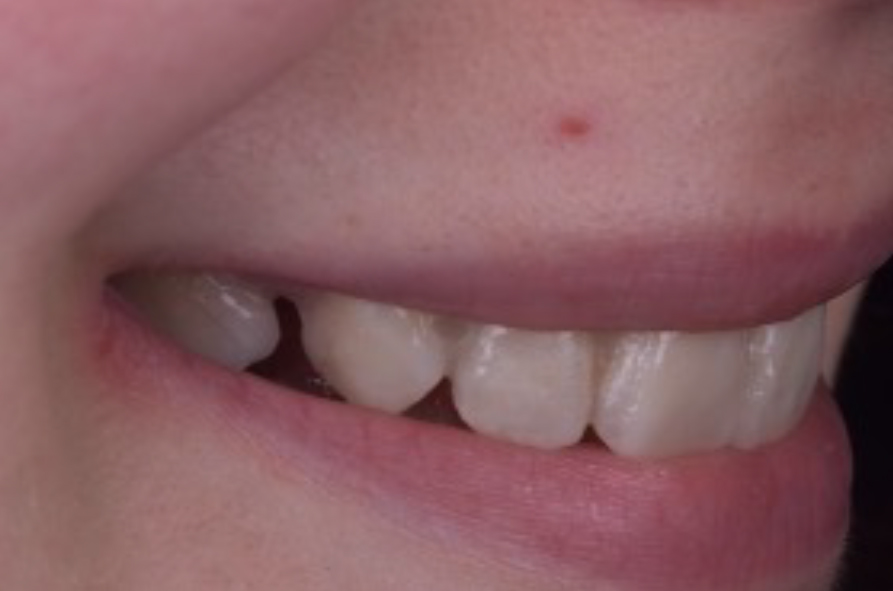
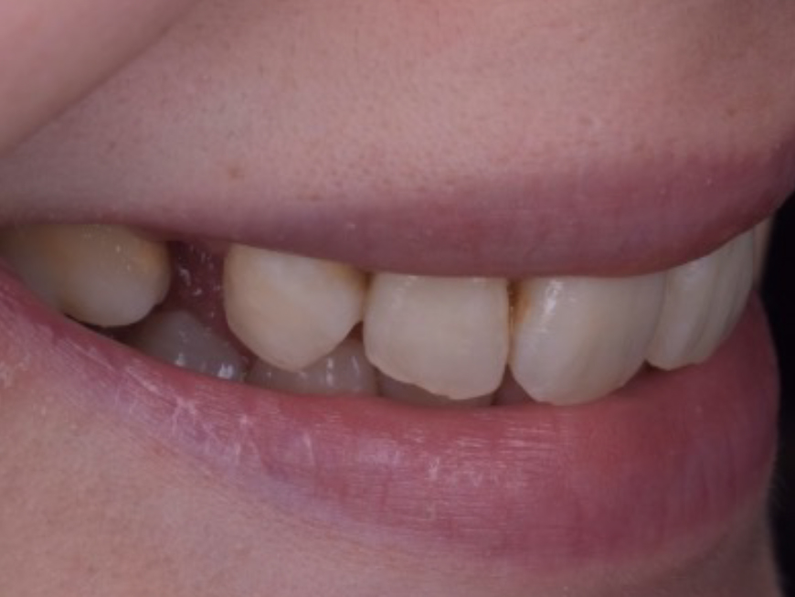
Figure 5. Left smile shot, which clearly shows the wear and chipping on the incisal edges.
A comprehensive examination was conducted, including dental and periodontal exams, soft tissue exams, photographs, radiographs, and an examination of the masticatory system. A smile analysis showed a canted midline and worn chipped incisal edges. The incisal plane was also canted. The gingival levels and their symmetry were acceptable. The axial inclinations of the centrals were both tilted to the patient's right, and the upper left lateral incisor was tipped buccally and distally. Figure 4 shows the extent of the space left by the missing UR5. This was a major concern for the patient.
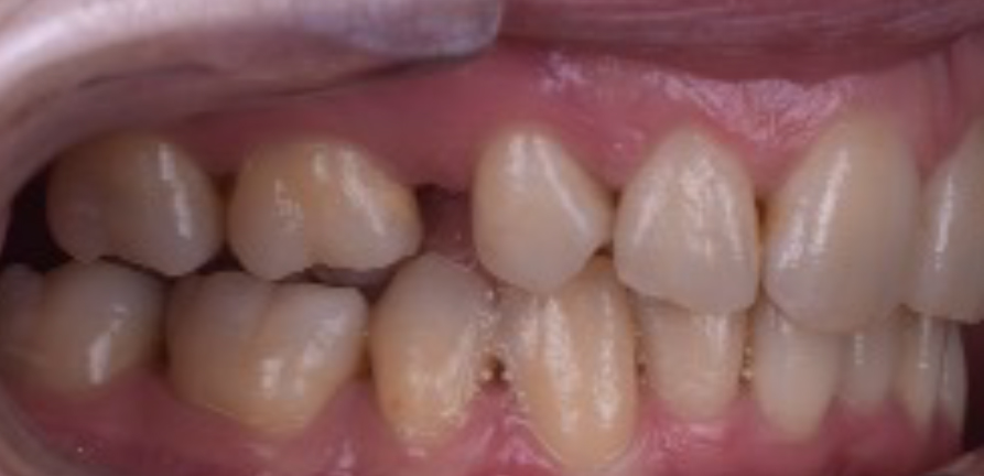
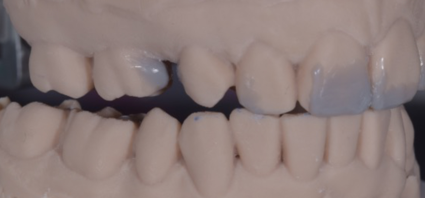
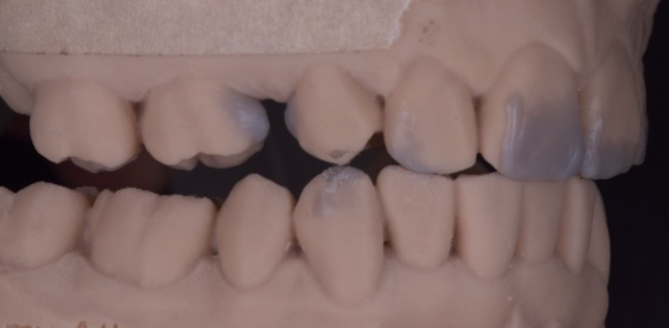
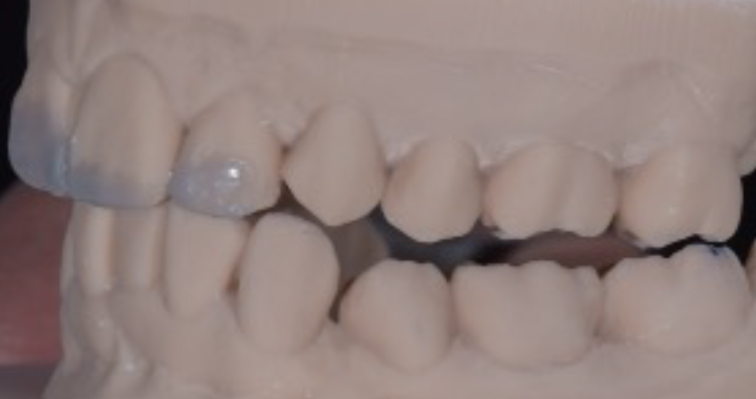
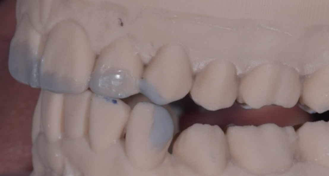
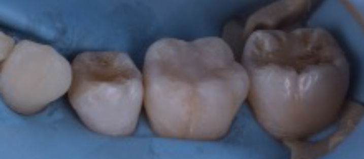
The retracted views in Figure 6, in occlusion, in maximum intercuspal position (MIP) show the poor interdigitation of the buccal segments and that the size of the space between UR6 and UR4 was insufficient for placement of a dental implant owing to the proximity of the adjacent roots. Close-up views in Figure 7 show the wear and chipping on the edges more clearly.
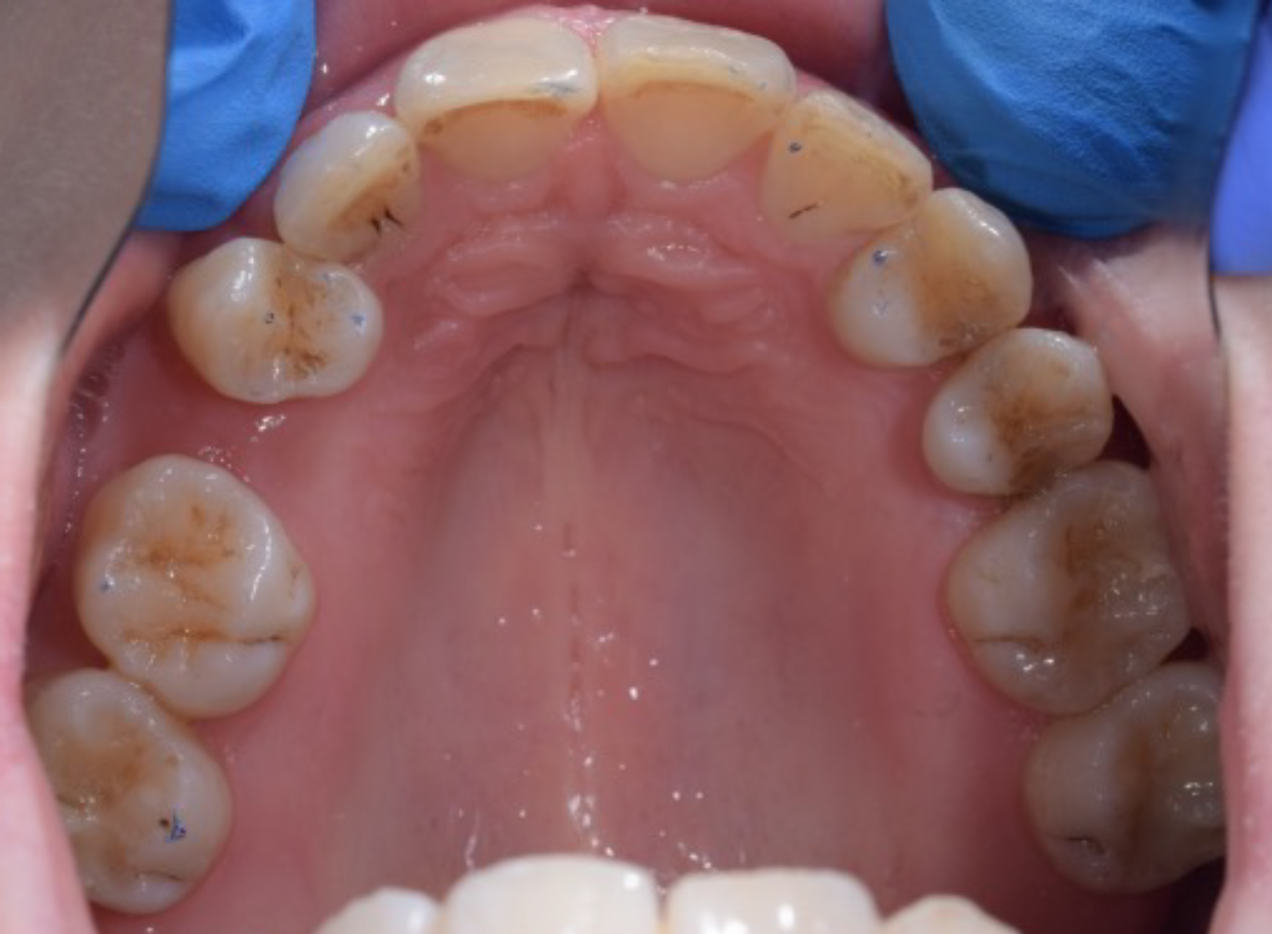
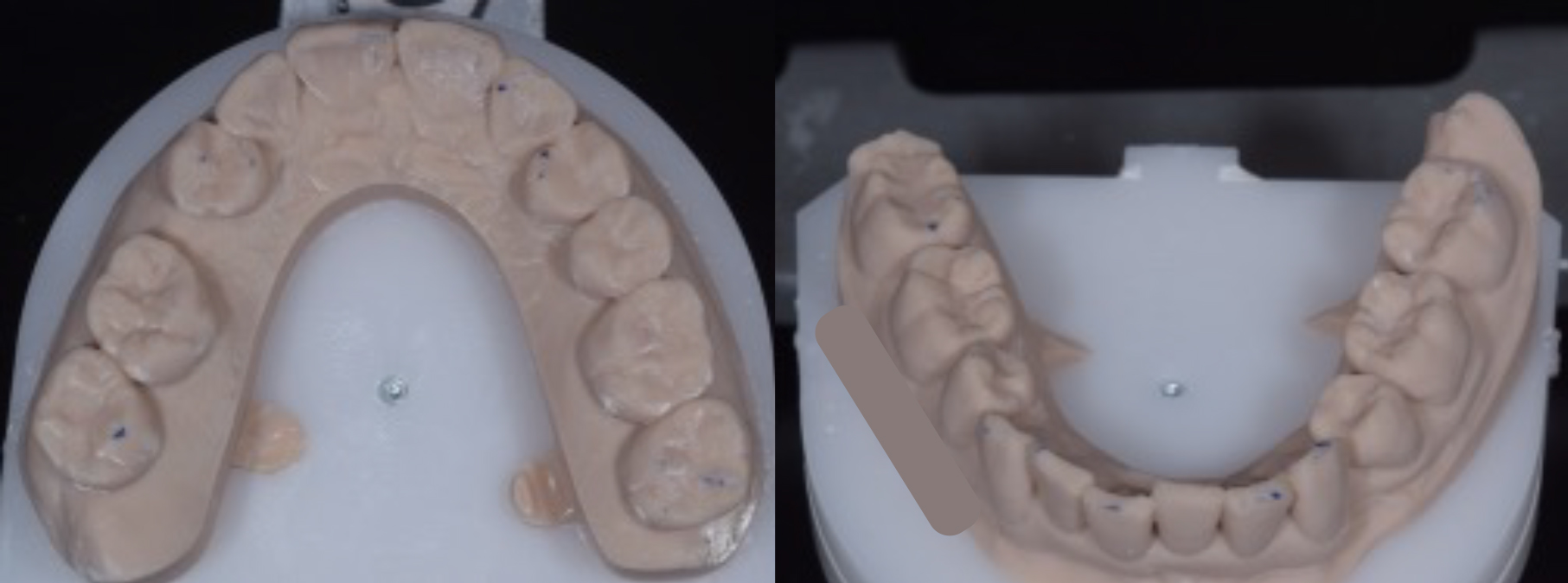
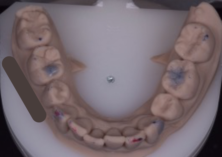
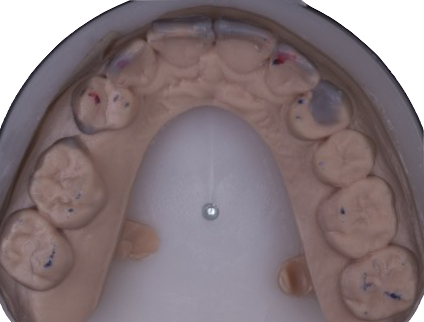
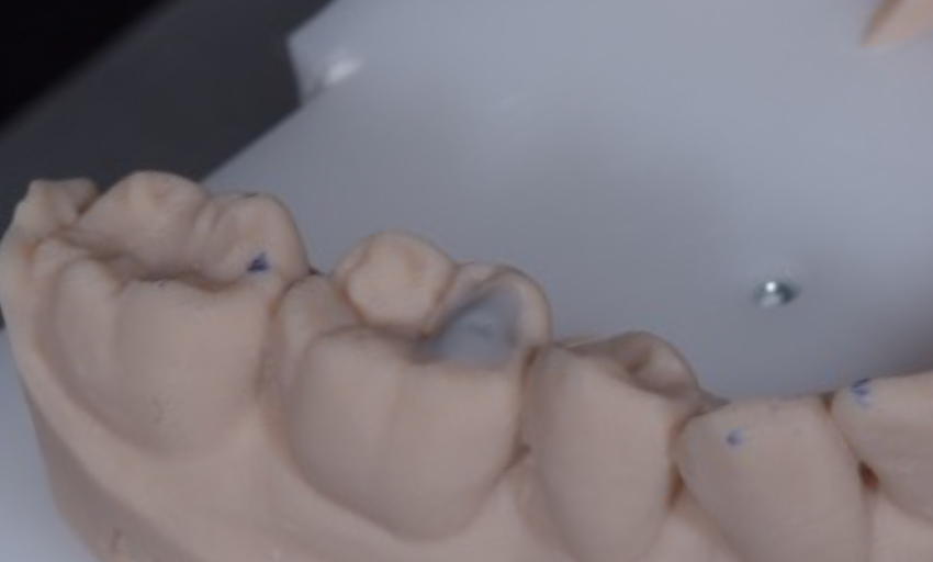
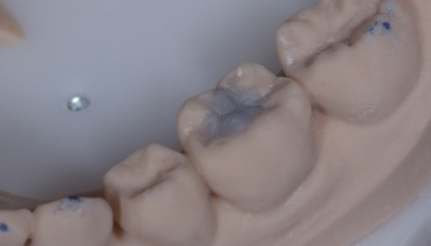
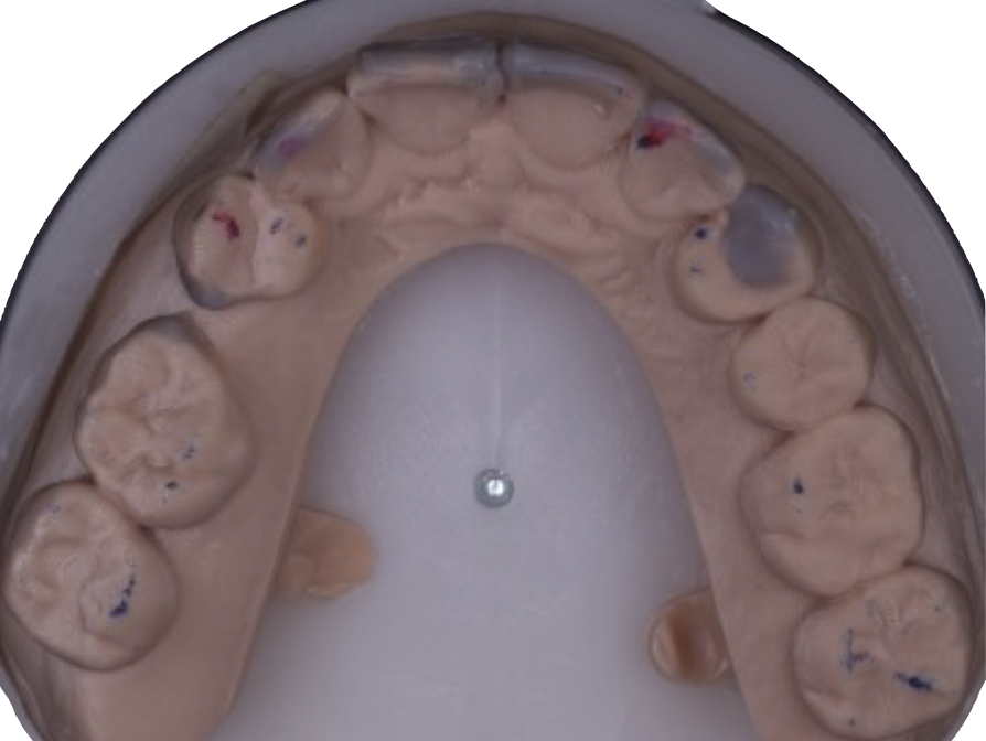
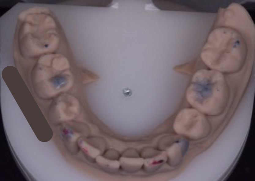
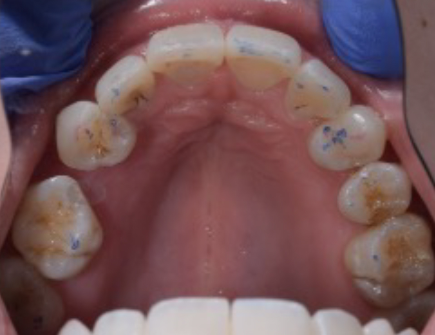
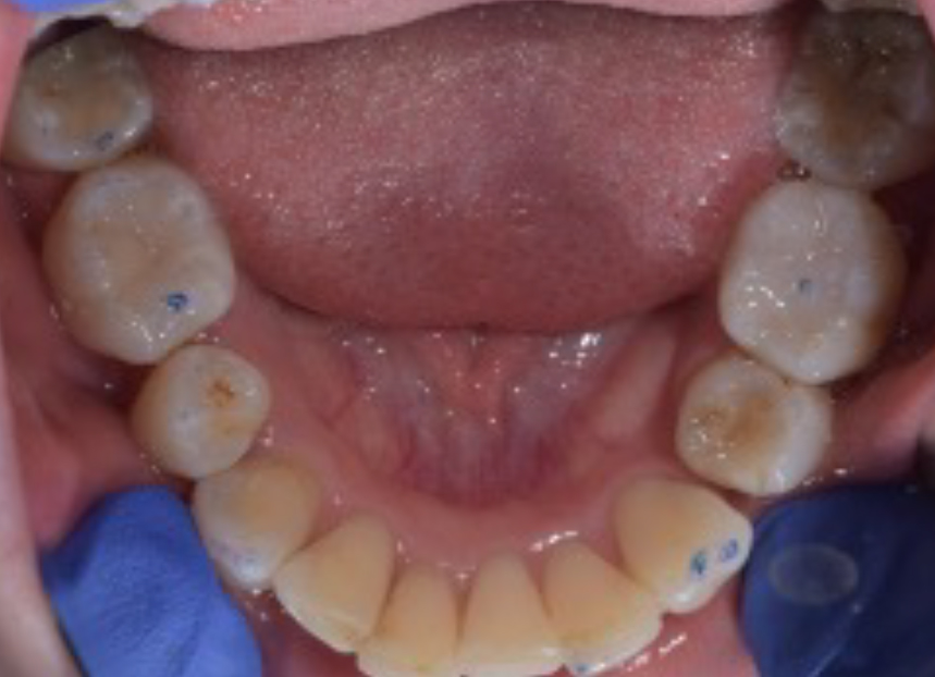
The initial occlusal examination included the examination of her temporomandibular joints and muscles of mastication. The results were unremarkable, with an acceptable range of motion. A leaf gauge was used to seat the condyles into centric relation and conduct a load test. The load test was negative, and the first point of contact in centric relation, the centric relation contact point (CRCP) was found to be on the UL4 palatal cusp against the LL3, with a small slide to MIP of less than 1 mm. Occlusal analysis showed that the patient had a repeatable MIP, indicated by the teeth occluding together in the same position every time she closed together. This repeatability is crucial because it allowed the use of the patient's MIP as the planning position for the occlusal aspect of treatment in this case. It acted as a reference and ensured the occlusion was not altered. In order for something not to be altered, first it must be examined and recorded. Figure 8 shows an occlusal view of the upper arch after the patient's occlusal contacts in MIP were marked. It is important to note that only four teeth were in contact, one of which was the UL2, which was exhibiting fremitus. To detect the fremitus, the pad of a gloved finger was placed on the buccal surface of the UL2, and the patient was asked to ‘tap tap tap’ her teeth together. If the UL2 can be felt being pushed outwards as it comes into contact with its antagonist tooth, it is documented as a positive finding for fremitus on the UL2. This is a sign of occlusal trauma, and although it is not always problematic, sometimes even serving as an adaptive mechanism to dissipate added load, in this particular case, the UL2's reduced root length made it unwise to maintain this tooth in fremitus. Additionally, the lack of occlusal contacts elsewhere meant that occlusal loads were being spread among fewer teeth, which could present a problem later on should the patient develop a clenching habit. The authors decided it would be prudent to fabricate and mount some study models to facilitate occlusal analysis and treatment planning. A facebow record was taken, along with scans of the upper and lower arches. The models were mounted in MIP, as this was a repeatable and comfortable position for the patient that clinicians could work to (Figure 9).
Figure 8. Existing MIP contacts shown in blue (UR7, UR4, UL2, UL4). Note the false-positive occlusal markings on UR6 and UR1.Figure 9. (a,b) Mounted models were fabricated to allow occlusal treatment planning.
A video was recorded of the patient going into different excursions. This was helpful for a couple of reasons:
It allowed checking and documentation of where any wear facets matched up. Note how the wear facets on UR2 and LR2 match up on the right excursion in Figure 10a. This strongly suggested that it was a movement that the patient reproduced because the surfaces must have been rubbed together to create the matching facets, and this would be likely to remain the case even after treatment. The patient had been in orthodontic treatment for a considerable amount of time, over 2 years, hence the wear facets matched up despite the teeth not being in their original pre-orthodontic positions.
Additionally, seeing in the video how the teeth moved across each other in the patient's mouth and comparing it to how the teeth moved across each other on the mounted models allowed verification of the mounting accuracy.
Figure 10. (a,b) Stills from the video (dynamic motion) analysis.
A period of approximately 6 months was allowed between the cessation of orthodontic treatment and the commencement of restorative treatment to check for the stability and repeatability of the current occlusion. A period of ‘settling’ is usually recommended by orthodontists to allow the occlusion to stabilise. During this time, the opinion of an implant dentist was sought, and tooth whitening was carried out.
Treatment options
The following options were discussed with the patient:
No additional treatment, accept and retain the orthodontic outcome;
Vital in-tray tooth whitening;
Use of direct composite resin to enhance the aesthetics of the teeth and correct the issues identified;
Use of indirect ceramic restorations to enhance the aesthetics of the teeth and correct the issues identified;
Address the occlusal deficiencies to improve force distribution, both in MIP and in excursion, to avoid overloading the teeth that had diminished periodontal support;
Regarding the residual space on the upper right, because implants were not feasible, the options were to either accept the space, use a removable or a fixed partial denture (resin bonded or conventional), or try to close the space restoratively with composite resin, understanding that the space could not be closed completely with this approach.
After a thorough discussion, the patient decided to undertake a whitening treatment, while a wax-up was created to visualise the desired aesthetic changes. The plan for the residual space was to apply direct composite resin as the treatment modality in the first instance owing to its minimally invasive nature. It was understood that should this fail to provide the necessary level of aesthetic improvement for the space, this part of the plan could be abandoned in favour of a resin-bonded bridge.
Treatment approach
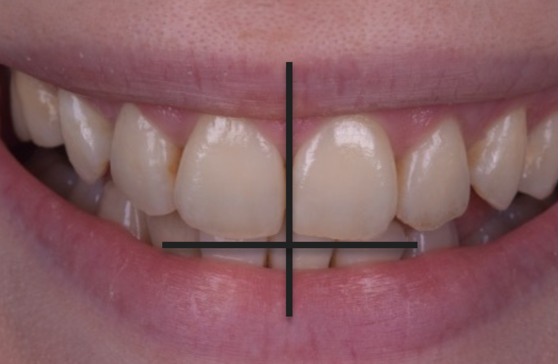
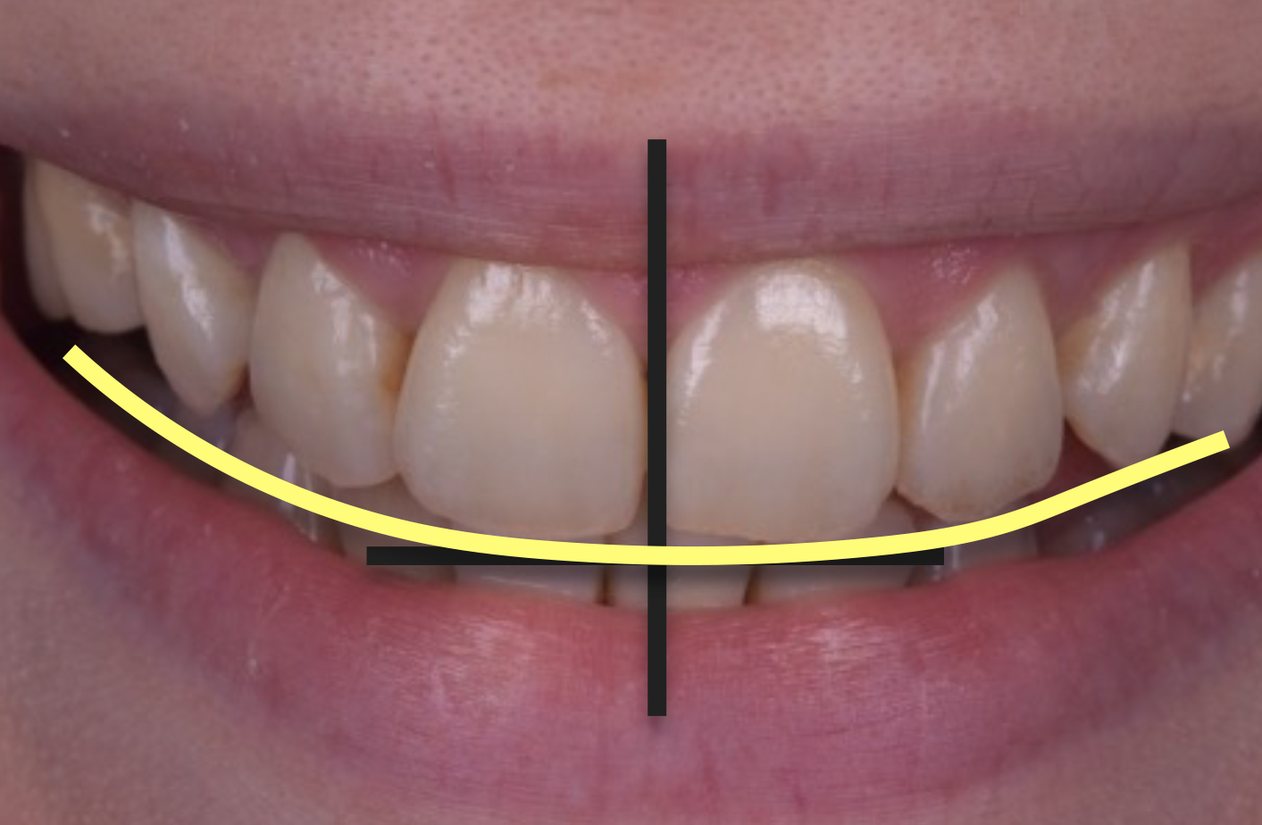
While the patient whitened her teeth using 16% carbamide peroxide in her nighttime removable retainers, a wax-up was carried out on the mounted models. The first step was to determine the new incisal edge position of the upper central incisors, ensuring their proper vertical position in the patient's face according to tooth display at rest and in smiling, and relative to the lower lip. The anteroposterior position was also determined relative to the lower lip, ideally placed just short of the wet–dry line of the vermillion border of the lower lip. Facial analysis using full-face portrait photos and videos was critical for this step. Figure 11 shows a zoomed-in view, with the vertical black line indicating the desired vertical orientation of the new midline, with the new incisal plane perpendicular to the new midline. Designing the new edges and midline in line with these parameters ensured the existing midline and incisal plane cants were eliminated. The smile curve was then designed (shown in yellow, Figure 12) to follow the lower lip and merge with the posterior occlusal plane. An added parameter to consider in this case was the decreased root length and decreased bony support, and hence the already unfavourable crown-to-root ratio. Adding length to the upper incisors was minimised, while still allowing room to achieve optimum aesthetics for a patient who had been through a long and arduous orthodontic journey. It was felt that she should, at the very least, have a nice smile at the end of it.
Figure 11. Desired vertical orientation of the midline and corresponding horizontal incisal plane.Figure 12. Overlayed smile curve (yellow line).
To retain ultimate control, the present authors prefer to wax-up such cases up themselves, because they are best placed to appreciate the changes required.
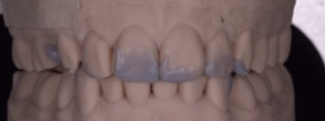
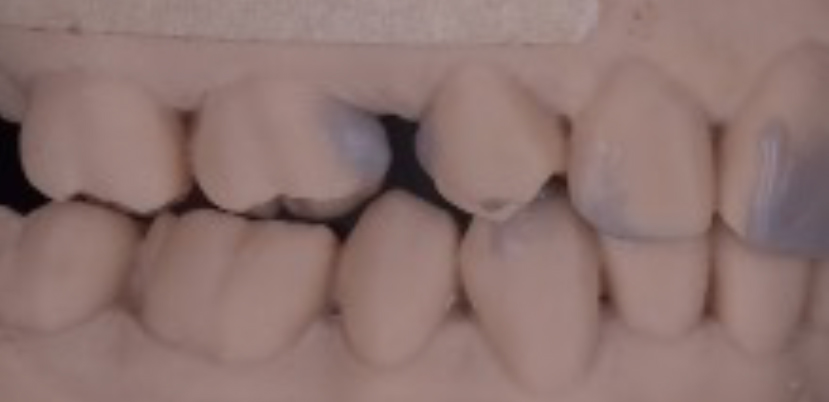
Figure 13 shows a rough wax-up of the desired aesthetic changes. The wax-up could be further refined; however, because all the facial aspects of the restoration were to be carried out freehand, there was little value in spending additional time on this. This point is being made to emphasise that this can be done within the remit of day-to-day dentistry.
Figure 13. (a,b) Rough wax-up.
The goal of the wax-up was to confirm that it is possible to straighten the midline, correct the incisal cant, and place the incisal edge position correctly in the patient's face. The mesial of the UR6 and the distal of the UR4 were waxed-up to try to close the space as much as possible without creating contours the patient could not clean. A mock-up could then be placed in the patient's mouth to see whether the amount of space closure was sufficient to satisfy the patient. If it did not satisfy, then alternative options, such as a resin-bonded bridge, could be considered.
The occlusal part of the wax-up had two distinct aspects that addressed load distribution in different scenarios: static (clenching) and dynamic (grinding). The fremitus on the UL2 informed the decision that load distribution during clenching needed to be addressed, while the wear on the edges of the teeth made it necessary to also carefully consider load distribution during lateral excursions/parafunction.
Figure 14 shows the occlusal aspect of the wax-up. This was, in fact, refined to a high degree because of the method chosen to transfer the occlusal design to the teeth, injection moulding. Injection moulding is a very accurate way of transferring the wax-up design from the model to the teeth in composite resin, and so, the final contour of the composite restorations will only be as good as the contour of the wax-up itself.
Figure 14. (a,b) Occlusal aspect of wax-up.
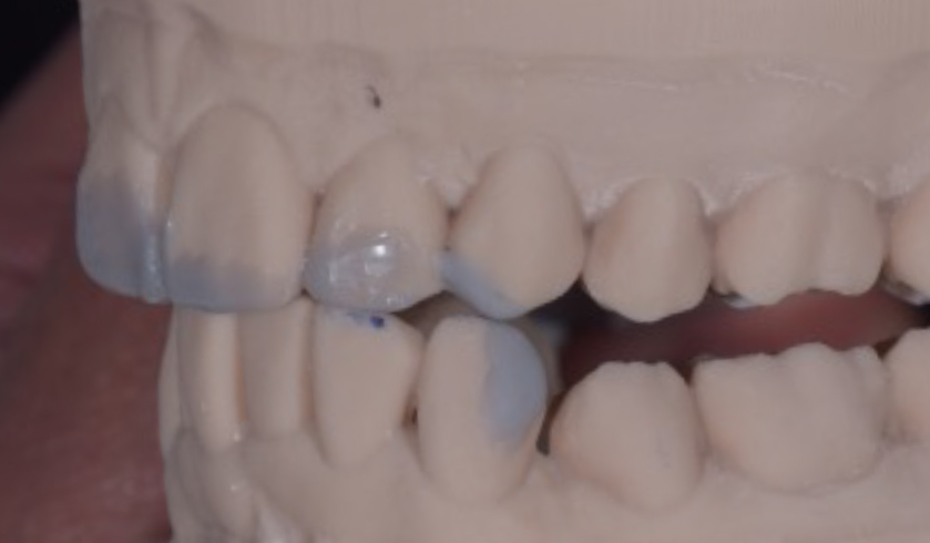
As for the static load distribution, the authors planned to add MIP contacts on two more posterior teeth, thus improving the load distribution by 50%. Contact on UL2 was slightly lightened to eliminate the fremitus in closure to MIP (‘tap tap tap’). In the patient's existing repeatable MIP position, two of the posterior opposing pairs of teeth had existing occlusal clearance sufficient for an occlusal stop to be created in composite resin that would be sufficiently thick. Two occlusal stops were waxed-up on LR6 and LL6 (Figure 15). This was carried out in a conformative manner without altering the vertical dimension of occlusion or the condylar position because of the existing occlusal clearance between some of the posterior teeth created by the discontinued orthodontic treatment.
Figure 15. (a,b) Wax-up of occlusal stops on the LR6 and LL6.
As for the dynamic relationship, the authors aimed to reduce the lateral load on the upper lateral incisors owing to their diminished root length and reduced periodontal support. They aimed to either remove the lateral load from the lateral incisors or at least share it between them and other teeth simultaneously.
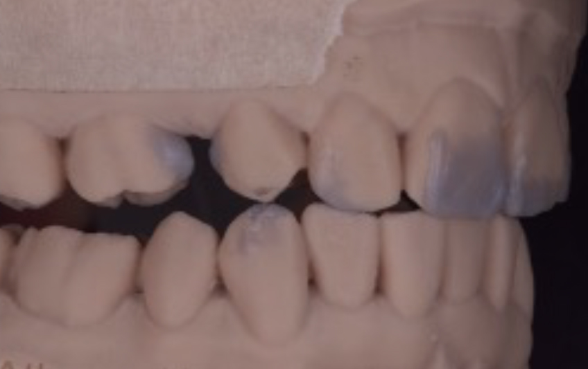
As shown in Figure 16a, it was only the UR2 that contacted the LR2 in right lateral excursion. The plan was to spread the load in this excursion, and therefore a contact was waxed-up on the UR4 and LR3 that would take some of the load in that excursion (Figure 16b). If the patient continued to move her mandible to the right, she would end up on her new central incisor edges. The handover of contact from UR4–LR3 to the upper and lower central incisal edges was made to be smooth. Figure 17 shows where this was replicated on the left-hand side. So as not to inadvertently disrupt the patient's slide from CRCP into MIP, care was taken to avoid placing the wax over the centric relation contact points on the UL4 palatal cusp and tip of the LL3.
Figure 16. (a,b) Right lateral excursion.Figure 17. (a,b) Left lateral excursion.
The next step was the moment of truth. With a putty stent of the wax-up, a temporary crown and bridge material (e.g. Luxatemp, DMG, Germany) was used to create an intra-oral mock up. This allowed the patient to preview the planned aesthetics and the clinician to confirm that the design goals have been met. Figure 18 shows the mock up in situ. The patient approved the overall aesthetics, and the midline and incisal cants had been corrected.
Figure 18. (a,b) Intra-oral mock up.
Figure 18a shows the anticipated partial closure of the residual spacing on the right-hand side. The patient was informed that there would still be some space present and was asked whether she was happy. The answer was a resounding ‘yes’, and the treatment plan was accepted. Consent was given to proceed with the definitive treatment.
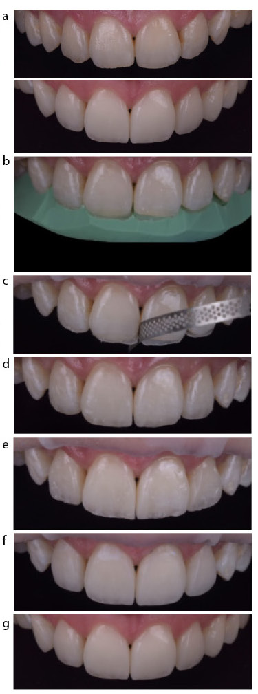
The upper anterior teeth were restored with direct composite resin layering using a palatal putty stent of the wax-up to transfer the new incisal edge position (Figure 19).
Figure 19. (a) Upper anterior composite restorations. (b–g) Layering steps and cant correction. (b) Palatal shell transfer from wax-up using putty index. (c) Correction of the cant by reducing the mesial of the UL1 with diamond strip. (d) Incisal effects. (e) Interproximal walls built with mylar pull technique. (f) Restorations finished, ready for polishing. (g) Final.
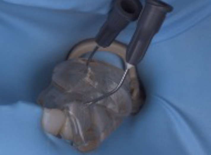
The occlusal aspects of the wax-up were transferred using the injection moulding technique. Clear polyvinyl siloxane (PVS) stents were made of the relevant areas of the wax-up using Exaclear (GC, Japan). Holes were made in the clear PVS stents for the introduction of the G-aenial Universal Injectable (GUI) (GC) composite resin tips, which were then placed into the stents ready for the restorative procedure. GUI was selected owing to its favourable handling, mechanical properties, and wear resistance.3
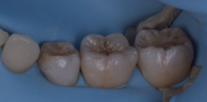
At the treatment appointment, the teeth were isolated with a rubber dam, and the LR6 and LL6 (Figure 20) were air abraded with 27-micron aluminium oxide. Appropriate etching and bond application was completed, and then the clear PVS stent was placed on the teeth with the flowable tips in place. The GUI syringes were then screwed onto the preloaded tips, and while the clear PVS was very firmly held onto the teeth, the GUI was slowly injected into the space in the stent. The tip was slowly withdrawn from the injection hole as the excess was expressed. Once removed, the firm seating of the stent was confirmed followed by curing for a full 60 seconds through the stent. The stent was removed once all restorations in the quadrant were completed, and the restorations were cured for a further 60 seconds. Provided that the etch and bonding agent had only been applied to where the composite needed to adhere (using the wax-up as a guide), the excess resin was extremely easy to remove with a number 12 scalpel blade and carbide burs.
Figure 20. (a–c) Procedure for LL6 composite.
Figure 21 shows the progression from wax-up to completed restorations, and the accuracy of transfer of the occlusal design using the injection moulding technique. There were now six occlusal contacts to take the load in a clench, and the UL2 no longer exhibited fremitus.
Figure 21. (a,b) The wax-up and (c,d) the completed restorations.
This case also highlighted that the articulator is far more accurate in the position at which the bite record is taken (i.e. MIP in this case) compared to any other position, such as excursion. The articulator is not an exact duplicate of the patient, and that limitation needs to be understood as clinicians must be prepared to make refinements in the mouth once the restorations have been placed. Figure 22 shows this clearly. It is clear that the articulator replicates the patient very closely in the left lateral excursion. However, in right lateral excursion, it is clear that what is seen on the articulator is not borne out in the patient's mouth. However, since the overall goal of reducing the load on the UR2 owing to its reduced root length was achieved, no further treatment was recommended. The lower anteriors were smoothed to achieve broad, flat contacts in edge-to-edge positions in all directions, ensuring that any transitions and contact handovers were smooth (Figure 23).
Figure 22. (a–d) Excursions on model versus in the patient's mouth.Figure 23. Edge-to-edge protrusive position.
Outcome
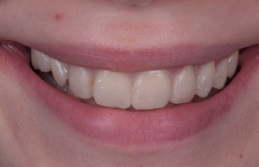
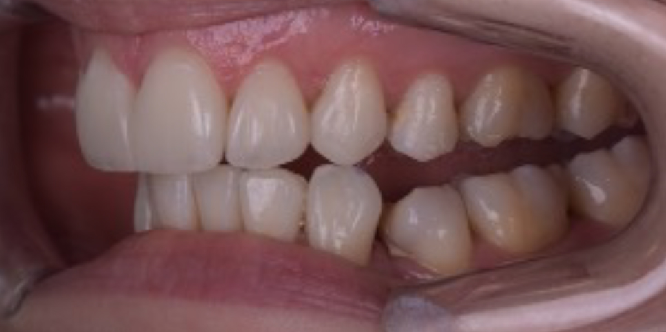
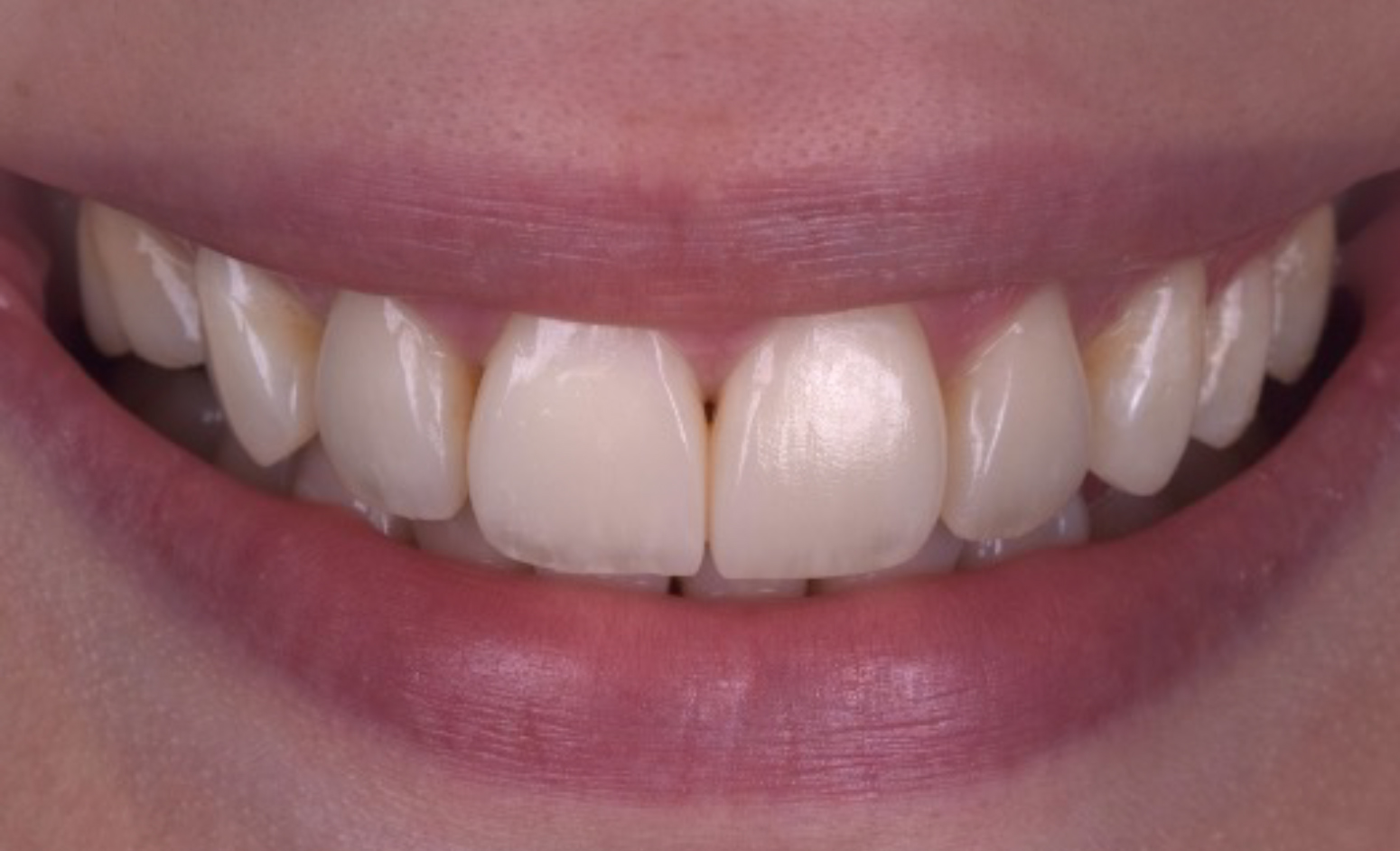
The comprehensive restorative intervention yielded remarkable outcomes, effectively addressing the patient's aesthetic concerns and restoring functional harmony to her dentition (Figure 24). The composite restorations seamlessly blended with the natural dentition, achieving life-like aesthetics while ensuring durable and long-lasting results. The patient's desire for a smaller space on the right-hand side without resorting to any preparation or prosthetic replacement was achieved. However, the option to transition to a resin-bonded bridge is still available should the patient wish to eliminate the space entirely in the future (Figure 25).
Figure 24. (a) Before and (b) after.Figure 25. (a) Before and (b) after lateral smile shots.
New upper and lower removable retainers were fabricated and the patient was instructed to wear them every night. Regular follow-up appointments were scheduled to monitor the stability of the restorations and ensure continued oral health maintenance. The latest review at 10 months showed that the occlusion was stable (with all contacts being the same as at the end of treatment) and that the mobility of the teeth with reduced root length had not increased.
Conclusion
This case exemplifies the successful integration of interdisciplinary collaboration, diligent treatment planning, and innovative restorative techniques in overcoming complex dental challenges. By combining aesthetic planning with functional rehabilitation, clinicians can achieve transformative outcomes, restoring both smiles and confidence to their patients.